PC100-2 Controller
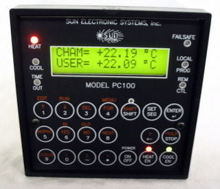
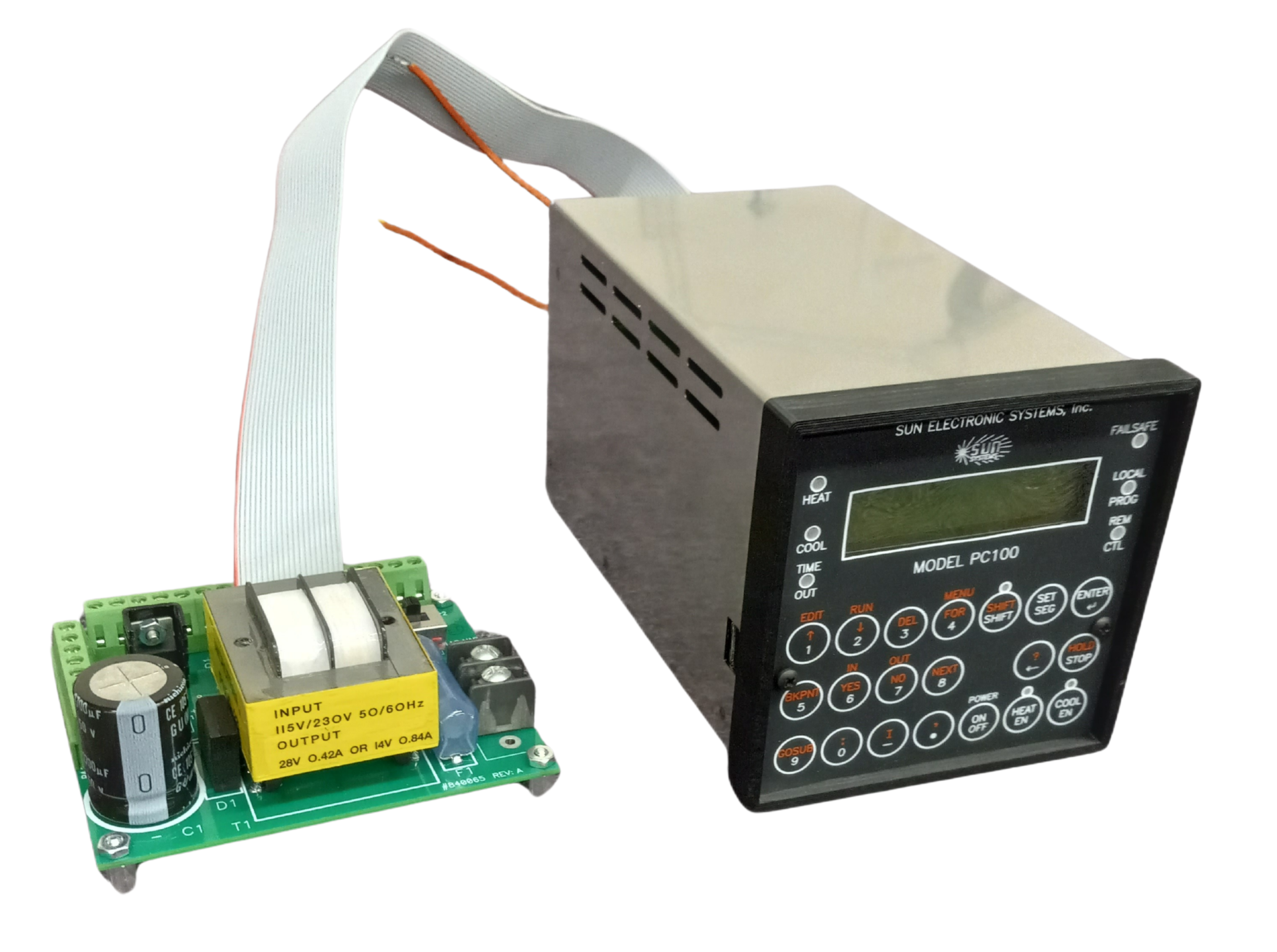
Sun Systems Model PC100-2 process controller is a dual sensor input, single channel control, 1/4 DIN, digital process controller with a host of advanced features. It incorporates advanced PID control routines that allow you to select which sensor, or sensor combination, will be used for control. The PC100-2 consists of the controller, an I/O board, remote panel and flat ribbon cables to connect to these assemblies. The unit was designed to be simple to set up and easy to use, but flexible enough to be used in a variety of applications. A typical application would be temperature control on channel 1 and monitor on channel 2.
Sensor Inputs
The PC100-2 is can be factory configured to accept a variety of sensors including: RTD, thermocouple, current and voltage input. The sensors are simply connected to the sensor input port located on the back of the PC100-2. Menus are also present to calibrate the sensors and to select units of measure for each channel. Each channel may be configured for degrees C or F.
Local and Remote Control
Programming can be performed locally from the 20 key front panel or remotely using the IEEE-488, RS232 or RS422 busses (all standard on every PC100-2). From the front panel you can set a single segment (Rate, Wait, Set) or an entire program can be entered via the local program EDIT mode. The PC100-2 provided for 10 separate local programs. A local program can typically have 100+ segments and uses a BASIC-like command set, including FOR-NEXT loops for cycling and GOSUB commands to call other programs as routines - features that allow for complex temperature profiles. These local programs can be entered by the front panel or uploaded from a host computer via the remote panel. All local programs and controller parameters are stored in non-volatile memory to retain all data. The controller has an on-board clock so that local programs can be run at a particular time of day. Remote control of the PC100-2 is performed by the IEEE-488, RS232 or RS422/485 interfaces.
Below are some sample Local Programs demonstrating the power and flexibility of the PC100-2.
Simple Two Segment Local Program
EDIT #0 (Store LP in location #0)
RATE = 10 (10C/min rate)
WAIT = 01:30:00 (Wait at 85C for 1.5 hrs.)
SET = 85
WAIT = 30 (Wait at -50C for 30 min.)
SET= -50
WAIT = 5 (Go to 25C for 5 min.)
SET = 25
END

RUN#0 (Execute program #0)
Local Program with Cycles
EDIT #1 (Store LP in location #1)
FOR I1 = 0,10 (Execute 10 cycles)
RATE = 10 (10C/min rate)
WAIT = 01:30:00 (Wait at 85C for 1.5 hrs.)
SET = 85
WAIT = 30 (Wait at -50C for 30 min.)
SET= -50
NEXT I1 (Repeat for 10 cycles)
WAIT = 5 (Go to 25C for 5 min.)
SET = 25
END

RUN#1 (Execute program #1 )
I/O
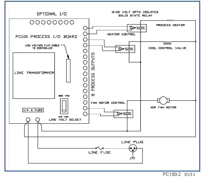
Bit I/0 to control on/off processes consists of eight 100mA open collector drivers capable of driving solid state relays (to connect to - terminal of the SSR) and a +5V regulator (to connect to + terminal). If requested, Sun can install a +12V regulator.These TTL outputs are easily accessible via the 8 position screw terminal on the process I/0 board that is supplied with the PC100-2. Three of the outputs are used solely by the PC100-2 controller - two for heat/cool and one for power on/off. The remaining 5 outputs are available for the user. One can be used for a compressor (selectable in menu) and one can be used as a cool boost (selectable in menu) while the remaining three can be used, for example, to control external relays. Outputs are turned on/off using the OUT command. The PC100-2 also has two TTL level inputs than can be read in using the IN command.
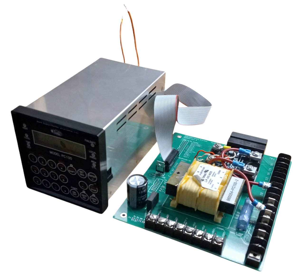
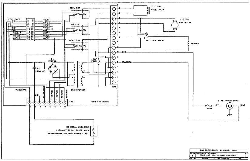
A TC02 I/O board can be substituted or purchased in addition to the standard PC100-2 I/O board to retro-fit Sun's obsolete TC02 controller with a PC100-2 as shown in the figure below.
Analog I/O
In addition to the bit I/0, the PC100-2 also provides one (0-5Vdc) analog input and two 0-3.3Vdc analog outputs (3.3Vdc is standard, but can be configured for +5Vdc if requested at the time the controller is ordered). One analog output is for charting, while the other one is for analog process control. The analog Inputs/ Outputs are controlled using input and output commands and are accessed from the 8 position screw terminal located on the PC100-2 I/O board.
PC100-2 Specs (pdf)
Power Consumption: 10 Watts
Input Voltage: 110/220vAC +- 10% (selectable on I/O board)
Line Frequency: 50/60 Hz
Dimensions: 3.81" (H) x 3.81" (W) x 6.62" (D)
1/4 DIN mounting Panel Cutout: 3.62" x 3.62"
Front Panel: 20 key, 16 x 2 line LCD
Sensor Malfunction: Open/Short probe detect
Controller Malfunction: Hardware watch dog timer
Process Errors: External Failsafe Input
Process Limits: Alarms for Upper, Lower and process deviation
limits
Line Voltage loss: Battery-Backed memory & time of day clock,
auto restart after power loss
Inputs: Two TTL level, One 5 volt 8 bit A/D, External Failsafe
input
Outputs: (8) 100mA Open Collector On/Off outputs, (2) 0-3.3 volt
analog outputs
(+5V if requested)
Control Technique: PID Algorithm, PWM on/off or 0-3.3v analog
control
Remote control: IEEE-488, RS232, RS422/485
SENSORS ACCEPTED: RTD (.385 or .392): -200C to +325C
J thermocouple: -200C to +760C
K thermocouple: -200C to +1250C
T thermocouple: -200C to +325C
Voltage: 0 to 5 Volt
Diode Resolution: selected range/32768 (.02 deg C typical)
Absolute Error Over Range (not including probe error): RTD: +-
.2C
J/K narrow: +- .35C
J/K wide: +- .5C
Voltage: +- 500 uV
Long Term Stability (per month) +- .025%