TEMPERATURE CHAMBER - EC10/11 MODEL WITH SWITCHING MATRIX DOOR
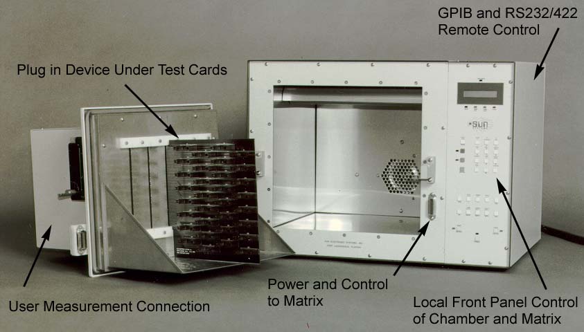
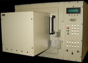
Sun Electronic System's EC10 and EC11 environmental chambers have the option of being equipped with a switching matrix door. The switching matrix provides automatic selection and measurement of components during temperature testing. It enhances productivity while providing precise accuracy and superior control. The switching matrix provides reliable temperature testing for high volume testing of components over a wide range of temperature (-184 °C to +200°C ).
The chamber door is
designed to hold up to 5 component boards within the
chamber environment and the switching matrix logic is
built into the outside of the door. The matrix control
boards facilitate the automatic switching and
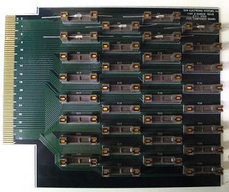
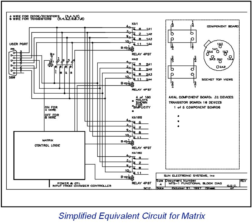
measurement of multiple devices under test. A diagram
of the control logic is provided to illustrate a sample
board used to test components.
Components such as transistors, resistors, capacitors, inductors, thermistors, diodes or any other 2, 3 or 4-leaded device are supported. The matrix door can hold and test up to 160 2-leaded axial components or up to 80 3,4-
leaded components with a 5-card
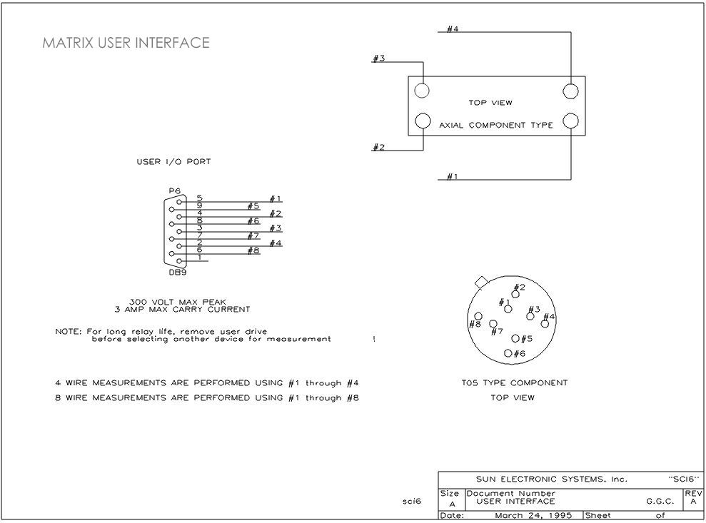
configuration. A Kelvin measurement path is provided to
the device under test. The user
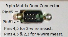
simply connects their device test equipment to the 9-pin connector (shown below)
provided on the front of the matrix door to take the measurement of each component.
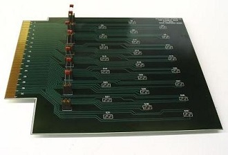
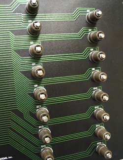
Devices under test may be selected automatically or individually by referring to the specific device number which is labeled for each socket on the device card. Thus, particular device(s) may be selected and measured independently if desired. Each device lead is provided with 2 electrically isolated traces and a Kelvin socket connection.
Selection of device under test is facilitated by a BASIC-like command set which may be issued either locally or remotely and allows for selection of each component individually or sequentially. All of these features provide for a fully automated test solution. Component card design and socket selection can be customized for the user's specific application. Sun Systems' will work with you to identify your testing needs and customize the switching matrix to your specifications.
The matrix commands to select the devices are as follows:
TO SELECT A 4-WIRE DEVICE FOR MEASUREMENT:
OUT4:n,m [n = device number (1 to 32)]
[m = board number (1 to 5)]
TO SELECT AN 8-WIRE DEVICE FOR MEASUREMENT:
OUT5:n,m [n = device number (1 to 8)]
[m = board number (1 to 5)
Sample Local Programs that can be entered locally or uploaded remotely to the EC10/11 matrix chamber to test and select the devices:
Example Local Program that will go to 155°C, wait for 5 1/2 minutes, then execute Program #2 (shown to the right), which will take meast's of all 160 components installed into each component card connector. Complete for 10 cycles.
EDIT#1
FOR I1=0,10 'Cycle 10 times
RATE=60 'Set rate of change of temperature during ramping
WAIT=0:5:30 'Stay at first temperature for 5 minutes, 30 seconds
SET=155 'Go to 155°C after 5 ½ minutes
GOSUB 2 'Go to program #2 (on right) as a subroutine, then
NEXT I1 'Loop until all 10 cycles complete
END
Example Local Program or subroutine to sequentially select each of the 32 components on each of the 5 component cards.
EDIT#2
FOR I3=1,6 'I3 will supply board number
FOR I2=1,33 'I2 will supply device number on board
OUT4: I2,I3 'Select each device to be measured
BKPNT I2 'Stop and allow operator to take reading
(press ENTER key on front panel to continue)
NEXT I2
NEXT I3 'End of nested loop
END
Sun offers a variety of component cards to hold 2,3 or 4 leaded components:
